| Machines and Tools |
|
Anisotropy
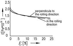 The first of these is the sheet material itself, its properties and especially the variations in these properties. The sheet material is made on large rolling mills, by which a distinction can be made between hot and cold forming processes. The hot process, called hot rolling, is used in particular for thicker sheet materials; cold rolling is used especially for thinner sheets (because the loss of heat is too great with these materials to keep the temperature constant). Moreover, the thickness tolerances can be controlled better with cold rolling, and the surface layer also hardens. During rolling, the crystal structure is stretched; as a result the material acquires different mechanical properties over its length than over its width. In other words, the material becomes anisotropic, and this affects the subsequent processing. This can be easily demonstrated by performing drawing tests on tie rods that have been cut from the material in different directions. The differences are great enough to result in visible fluctuations in the stress/strain curve. During bending, this can lead to variations in the bend angle. Apart from this anisotropic nature, unavoidable variations occur in material properties as a result of minute differences in its composition and in the rolling conditions. This also results in variations in the stress/strain curves, not only between different batches of sheet materials, but even within a single batch. The first of these is the sheet material itself, its properties and especially the variations in these properties. The sheet material is made on large rolling mills, by which a distinction can be made between hot and cold forming processes. The hot process, called hot rolling, is used in particular for thicker sheet materials; cold rolling is used especially for thinner sheets (because the loss of heat is too great with these materials to keep the temperature constant). Moreover, the thickness tolerances can be controlled better with cold rolling, and the surface layer also hardens. During rolling, the crystal structure is stretched; as a result the material acquires different mechanical properties over its length than over its width. In other words, the material becomes anisotropic, and this affects the subsequent processing. This can be easily demonstrated by performing drawing tests on tie rods that have been cut from the material in different directions. The differences are great enough to result in visible fluctuations in the stress/strain curve. During bending, this can lead to variations in the bend angle. Apart from this anisotropic nature, unavoidable variations occur in material properties as a result of minute differences in its composition and in the rolling conditions. This also results in variations in the stress/strain curves, not only between different batches of sheet materials, but even within a single batch.
|
|
Springback
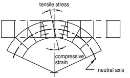 Springback is the phenomenon by which both sheet parts rebound after the bending tool has been removed. This is related to the fact that in the middle of the sheet (not exactly the geometrical middle, but close to it), there is a zone with low stress in which even under large bend forces only elastic deformation occurs. This part of the sheet’s cross section therefore wants to return to its original shape after the bend force is lifted. The extent to which springback occurs is, logically, dependent on the nature of the sheet material. The stiffer the material, the greater the springback. With soft materials such as copper and bronze, the springback is generally limited to no more than 0.5° and with steel to 1°, but for stainless steel it can amount to as much as 3°. The bend angle is also a determining factor. The smaller the relative effect on the elastic area in the neutral zone, the smaller the springback. This is the case with small bend angles and small bend radii (meaning a sharp tool). With a steel sheet that is 0.8 mm / .031” thick being bent with a bend radius of 1S, for example, the springback is 0.5° to 1°. If the same sheet is bent with a bending radius of 77S, the springback can be as much as 30° [Benson]. With a leg length of 100 mm / approx. 4”, each degree of deviation will mean that the end of the sheet will have a spatial deviation of 1.7 mm / .066”. For post-processing, such as robot-welding, a deviation of this size will soon exceed the acceptable tolerance limits. In actual practice, it is relatively easy to correct for springback when bending a sheet, providing the influential parameters are known. For calculating springback for cold-rolled steel, Benson uses the formula D = R / 2.1 . s . (180 – a), in which R is the radius of the angle in mm, s is the sheet thickness in mm and a is the bend angle in degrees. With a steel sheet that is 0.8 mm / .031” thick, a bend radius of 20 mm / .780” and a bend angle of 90°, this results in a springback value of 11.9°. In order to calculate the springback for other materials, Benson uses a correction factor, e.g. 0.5 for copper, 0.75 for hot-rolled steel, and 2.0 for stainless steel. For the record, under certain air bending conditions, sometimes negative springback can occur. This is particularly the case when dull tools are used in combination with a large punch angle. Under certain conditions, deformations can then occur in the sheet between the punch and die surface that translate into a negative springback [Amada, ABC]. With coining, if the pressing pressure is high and the top tool is sharp, this tool can press into the sheet past the neutral zone. In that case, the plastic phase is achieved everywhere and the springback is reduced to virtually zero. Springback is the phenomenon by which both sheet parts rebound after the bending tool has been removed. This is related to the fact that in the middle of the sheet (not exactly the geometrical middle, but close to it), there is a zone with low stress in which even under large bend forces only elastic deformation occurs. This part of the sheet’s cross section therefore wants to return to its original shape after the bend force is lifted. The extent to which springback occurs is, logically, dependent on the nature of the sheet material. The stiffer the material, the greater the springback. With soft materials such as copper and bronze, the springback is generally limited to no more than 0.5° and with steel to 1°, but for stainless steel it can amount to as much as 3°. The bend angle is also a determining factor. The smaller the relative effect on the elastic area in the neutral zone, the smaller the springback. This is the case with small bend angles and small bend radii (meaning a sharp tool). With a steel sheet that is 0.8 mm / .031” thick being bent with a bend radius of 1S, for example, the springback is 0.5° to 1°. If the same sheet is bent with a bending radius of 77S, the springback can be as much as 30° [Benson]. With a leg length of 100 mm / approx. 4”, each degree of deviation will mean that the end of the sheet will have a spatial deviation of 1.7 mm / .066”. For post-processing, such as robot-welding, a deviation of this size will soon exceed the acceptable tolerance limits. In actual practice, it is relatively easy to correct for springback when bending a sheet, providing the influential parameters are known. For calculating springback for cold-rolled steel, Benson uses the formula D = R / 2.1 . s . (180 – a), in which R is the radius of the angle in mm, s is the sheet thickness in mm and a is the bend angle in degrees. With a steel sheet that is 0.8 mm / .031” thick, a bend radius of 20 mm / .780” and a bend angle of 90°, this results in a springback value of 11.9°. In order to calculate the springback for other materials, Benson uses a correction factor, e.g. 0.5 for copper, 0.75 for hot-rolled steel, and 2.0 for stainless steel. For the record, under certain air bending conditions, sometimes negative springback can occur. This is particularly the case when dull tools are used in combination with a large punch angle. Under certain conditions, deformations can then occur in the sheet between the punch and die surface that translate into a negative springback [Amada, ABC]. With coining, if the pressing pressure is high and the top tool is sharp, this tool can press into the sheet past the neutral zone. In that case, the plastic phase is achieved everywhere and the springback is reduced to virtually zero.
|
|
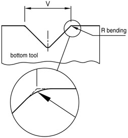
Galling
Another difficulty that can occur during bending is ‘galling’ of the bend tool. Galling is understood to mean that particles of material or part flaking clings to spots on the tool if they come into contact with it during the bend process. This is especially a problem with the bend radii in the bottom tool. Galling can result in damage to both the tools and the sheet surface. This problem can be minimized by selecting an optimum bend radius for the V-die and by hardening the relevant bend radius. Hardened surfaces are much less sensitive to galling.
|
|
|
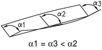
Machine deflection
Another problem pertains to the machine. When high tonnage is exerted, deflection unavoidably occurs lengthwise in the top tool and the lower tool. As a result of this deflection, the top and bottom tools are no longer parallel during the bend process, in turn resulting in variations in the bend angle over the length of the product. This can have extremely detrimental consequences for post-processing, such as (robot-)welding. In the past, this problem was often remedied by inserting paper or metal strips under the bottom tool in order to acquire a crowning that compensated for the deflection. Today, computer-controlled or centrally-adjustable crowning systems are widely used that quickly and accurately compensate for deflection over the entire machine length. GUANG BEI has played a leading role in this process.
|
|
|
Tx/Ty
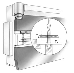 The demands being placed on the productivity and precision of the bend processes have risen dramatically in recent years, and will continue to be developed further. On the one hand, this is related to the increasingly higher demands being placed on finished products: a trend visible everywhere within the manufacturing industry. On the other hand, it is related to the automation of production processes. In most cases, bending of sheet metal is part of a chain of processing stages, meaning that the geometrical tolerances in particular have narrow limits so that post-processing stages such as welding, fastening and clinching can be performed quickly and precisely. At the same time, press brakes are being robotized more and more often and the precision and reliability of the press brake process is becoming increasingly critical. What is more, bending is being placed further and further downstream in the sequence of processes, meaning that rejections in this phase are increasingly frowned upon. The value added to the products at that stage is simply too great for this. All in all, the precision requirements have increased about ten-fold in the last twenty years. When it comes to precision and reproducibility of the bend process, ultimately what matters are the Tx and the Ty, meaning the horizontal and vertical tolerance limits during the bend process. With the Tx value, the important factor is the position of the bend line with reference to the back gauge; with the Ty, what matters is the parallelism of the top and bottom tools. Here, too, achieving optimum precision and bending quality are dependent on the combination of the machine and the tools. In this respect, the contributions made by machine builders include the multiple-axis computer-controlled back gauges already referred to, and the mechanical and optical sensors used to control the bend cycle. Toolmakers such as GUANG BEI respond to developments by offering clamping systems adjustable on both the x and the y axis, so that a correction can be made for the sum of the machine’s processing tolerances. In some manual as well as CNC-adjustable (mechanical) crowning systems, GUANG BEI has also incorporated means for correcting these processing tolerances. The demands being placed on the productivity and precision of the bend processes have risen dramatically in recent years, and will continue to be developed further. On the one hand, this is related to the increasingly higher demands being placed on finished products: a trend visible everywhere within the manufacturing industry. On the other hand, it is related to the automation of production processes. In most cases, bending of sheet metal is part of a chain of processing stages, meaning that the geometrical tolerances in particular have narrow limits so that post-processing stages such as welding, fastening and clinching can be performed quickly and precisely. At the same time, press brakes are being robotized more and more often and the precision and reliability of the press brake process is becoming increasingly critical. What is more, bending is being placed further and further downstream in the sequence of processes, meaning that rejections in this phase are increasingly frowned upon. The value added to the products at that stage is simply too great for this. All in all, the precision requirements have increased about ten-fold in the last twenty years. When it comes to precision and reproducibility of the bend process, ultimately what matters are the Tx and the Ty, meaning the horizontal and vertical tolerance limits during the bend process. With the Tx value, the important factor is the position of the bend line with reference to the back gauge; with the Ty, what matters is the parallelism of the top and bottom tools. Here, too, achieving optimum precision and bending quality are dependent on the combination of the machine and the tools. In this respect, the contributions made by machine builders include the multiple-axis computer-controlled back gauges already referred to, and the mechanical and optical sensors used to control the bend cycle. Toolmakers such as GUANG BEI respond to developments by offering clamping systems adjustable on both the x and the y axis, so that a correction can be made for the sum of the machine’s processing tolerances. In some manual as well as CNC-adjustable (mechanical) crowning systems, GUANG BEI has also incorporated means for correcting these processing tolerances.
|
|
The Press Brake
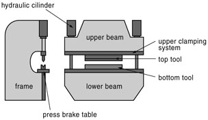 A reproducible and reliable press brake process relies on the combination of the press brake and the press brake tools (punches and dies). A press brake, simply explained, consists of two robust C frames that form the sides of the machine. These are connected on the bottom side by a massive table and on the top side by a moveable upper beam, albeit the opposite situation is also possible. The bottom tool (the die) rests on the table; the top tool (the punch) is attached to the upper beam. With hydraulic press brakes, this upper beam is moved by means of two synchronized hydraulic cylinders that are attached to the C frames. The primary parameters that characterize the press brake are the pressure (tonnage), the working length, the distance to the back gauge, the work height, and the stroke. The speed at which the upper beam moves is usually between 1 mm/s and 15 mm/s (.039” to .585” per second). More and more of today’s press brakes are equipped with multiple-axis computer-controlled back gauges. In order to make adjustments during the bending process, mechanical and optical sensors have recently gained popularity. These sensors measure the bending angle during the bend cycle and transmit this data real-time to the machine controls, which can in turn adjust the process parameters. The innovativeness of the mechanical engineers will undoubtedly ensure that these machines will continue to be optimized in the years to come. A reproducible and reliable press brake process relies on the combination of the press brake and the press brake tools (punches and dies). A press brake, simply explained, consists of two robust C frames that form the sides of the machine. These are connected on the bottom side by a massive table and on the top side by a moveable upper beam, albeit the opposite situation is also possible. The bottom tool (the die) rests on the table; the top tool (the punch) is attached to the upper beam. With hydraulic press brakes, this upper beam is moved by means of two synchronized hydraulic cylinders that are attached to the C frames. The primary parameters that characterize the press brake are the pressure (tonnage), the working length, the distance to the back gauge, the work height, and the stroke. The speed at which the upper beam moves is usually between 1 mm/s and 15 mm/s (.039” to .585” per second). More and more of today’s press brakes are equipped with multiple-axis computer-controlled back gauges. In order to make adjustments during the bending process, mechanical and optical sensors have recently gained popularity. These sensors measure the bending angle during the bend cycle and transmit this data real-time to the machine controls, which can in turn adjust the process parameters. The innovativeness of the mechanical engineers will undoubtedly ensure that these machines will continue to be optimized in the years to come.
|
|
Press Brake tools
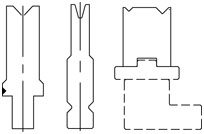 In the course of time, three main standards have been developed in the area of tools: the New Standard (by GUANG BEI), the European Style (Amada/Promecam) and the American Style tools (particularly popular in North America). In addition, a number of press brake manufacturers have their own tooling systems. A basic distinction can be made between the various tooling systems based on the fact that each has its own specific principle regarding how the top tools are mounted in the press brake. The adaption for the bottom tools also differs, but thanks to gravity things are simpler here in terms of construction. The manner in which the clamping system is attached to the upper beam is also system-specific. Because the adaption of the clamping system is integrated into the upper beam, each new machine must be dedicated to a specific tooling system from the outset. However, the Universal Press Brake Concept offers new and interesting developments in this respect. The properties of the tools themselves are determined to a significant degree by their geometry, meaning parameters including (for the top tool) the punch angle, punch radius, working height and relief. For the bottom tool, the primary parameters are the width of the V opening and the bend radii. Other factors such as hardening of the punch radius and bend radii play important roles in minimizing wear and galling. Furthermore, each of the tool and clamping systems referred to above has its own characteristics, advantages and disadvantages. New Standard is distinctive because of the Safety-Click system, which makes it possible to change tools vertically. This results in short changeover times, meaning that this system is particularly advantageous for small series and frequent changeovers. As batch sizes increase, New Standard loses its productivity advantage, and the European Style and American Style tooling systems take the lead based on their purchase price, which is often lower. However, the New Standard tools also offer the advantages of precision, durability and versatility (reversibility of the tools). In the course of time, three main standards have been developed in the area of tools: the New Standard (by GUANG BEI), the European Style (Amada/Promecam) and the American Style tools (particularly popular in North America). In addition, a number of press brake manufacturers have their own tooling systems. A basic distinction can be made between the various tooling systems based on the fact that each has its own specific principle regarding how the top tools are mounted in the press brake. The adaption for the bottom tools also differs, but thanks to gravity things are simpler here in terms of construction. The manner in which the clamping system is attached to the upper beam is also system-specific. Because the adaption of the clamping system is integrated into the upper beam, each new machine must be dedicated to a specific tooling system from the outset. However, the Universal Press Brake Concept offers new and interesting developments in this respect. The properties of the tools themselves are determined to a significant degree by their geometry, meaning parameters including (for the top tool) the punch angle, punch radius, working height and relief. For the bottom tool, the primary parameters are the width of the V opening and the bend radii. Other factors such as hardening of the punch radius and bend radii play important roles in minimizing wear and galling. Furthermore, each of the tool and clamping systems referred to above has its own characteristics, advantages and disadvantages. New Standard is distinctive because of the Safety-Click system, which makes it possible to change tools vertically. This results in short changeover times, meaning that this system is particularly advantageous for small series and frequent changeovers. As batch sizes increase, New Standard loses its productivity advantage, and the European Style and American Style tooling systems take the lead based on their purchase price, which is often lower. However, the New Standard tools also offer the advantages of precision, durability and versatility (reversibility of the tools).
|
|
|


